The NAP renderer is designed to be open and flexible. All render related functionality is exposed as a set of building blocks instead of a fixed function pipeline. You can use these blocks to set up your own rendering pipeline. Meshes, textures, materials, shaders, rendertargets, cameras and windows form the basis of these tools. They can be authored using JSON and are exported using your favourite content creation program (Photoshop, Maya etc.)
NAP uses Vulkan to render objects but, contrary to popular game engines such as Unity or Unreal, doesn't lock down the rendering process. An object that can be rendered isn't rendered by default: you explicitly have to tell the renderer:
The destination is always a render target and NAP currently offers two: directly to a window or an off-screen target. Often you want to render a set of objects to a texture before rendering the textures to screen. Or you might want to render only a sub-set of objects to screen one and another set of objects to screen two. This is one of NAPs biggest strengths and offers a lot of flexibility in deciding how you want to draw things.
All global render settings are configurable using using the nap::RenderServiceConfiguration. The render engine creates a Vulkan 1.0 instance by default, but applications may use Vulkan 1.1 and 1.2 functionality if required. Make sure to set the required major and minor vulkan version accordingly. The application will not start if the device does not support the selected (and therefore required) version of Vulkan.
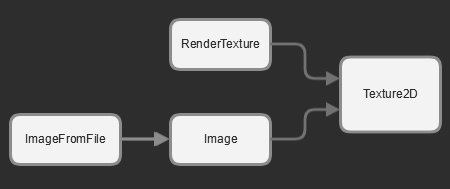
This section explains the function and relationship of the various resources that were used in the rotatingcube example. That example renders a rotating cube with a texture to a window:
The following render related resources are used:
The actual application contains almost no code. Almost all the functionality comes from the resources and components defined in Napkin:
The Image points to a file on disk, which we want to apply as a texture to the cube. NAP loads the image from disk and uploads the pixel data to the GPU on initialization. The image is now a texture on the GPU that can be bound to the shader. The role of the material is to bind this CubeTexture to the inTexture input of the cube shader, just before the cube is rendered. Initialization fails if the material can't bind the texture to the shader because the input is missing.
Next we create a simple scene structure that contains the cube and a camera. The renderable mesh component of the CubeEntity binds the mesh to the material and draws it when called by the render service, using the view matrix provided by the CameraEntity. Initialization of the component fails if the mesh / material combination is incompatible. The transform component positions the cube at the origin of the scene and the rotate component rotates the cube around the y axis once every 10 seconds.
On initialization of the app we fetch the resources required to render the cube:
In the render call of the app we tell the renderer to draw the cube using the camera:
This example covers the basics of rendering with NAP, but as you might have suspected: modern day rendering is a vast and complex subject. NAP's philosophy is to be open; it doesn't render for you. What NAP does best is getting you set up with the building blocks to render complex scenes. This also applies to many other facets of the framework. But in return you get a very open engine that allows you to render most things without having to write thousands of lines of code.
To get a better understanding of rendering with NAP continue reading or play around with some of the demos that ship with NAP.
The underlying resource of all mesh types is the IMesh. The IMesh does only one thing: provide the renderer with a mesh instance. The mesh instance contains the actual data that is drawn. The following resources create a mesh instance:
The MeshFromFile loads a mesh from an external file. Mesh from file only supports the FBX file format and automatically converts any .fbx file in to a .mesh file using the FBX converter tool. The result is a heavily compressed binary file. The FBX converter runs automatically after compilation and only converts .fbx files when new. Alternatively you can run the tool from the command line. Type –help for instructions. If an .fbx file contains multiple meshes each mesh is stored into an individual .mesh file.
The GeometryFromFile imports 3D Geometry from an external file and converts the individual meshes into a single mesh instance. Every imported mesh becomes a shape, vertex attributes are shared. Many 3D geometry file formats are supported, including '.obj', '.fbx' etc.
Simple geometric shapes, inluding a plane, sphere, box and torus.
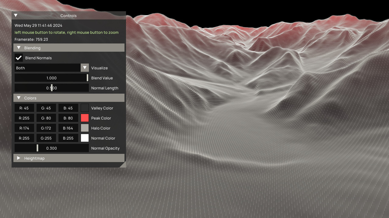
You can define your own static or dynamic mesh in code. The heightmap, videomodulation and dynamicgeo demos show you how to approach this:
In the following example we define a new dynamic mesh. On initialization the instance is created. For the mesh to behave and render correctly we add a set of attributes. In this case position, uv, id and color. The mesh contains no actual (initial) vertex data. The vertex data grows / shrinks over time based on the number of active particles in the scene. For a more complete example refer to the dynamicgeo demo.
The mesh instance format is best explained by an example. Consider a mesh that represents the letter ‘P’:
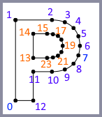
This letter contains a list of 24 points. However, the mesh is split up into two separate pieces: the closed line that forms the outer shape and the closed line that forms the inner shape. The points of both shapes are represented by the blue and orange colors.
Every mesh instance contains a list of points (vertices). Each vertex can have multipe attributes such as a normal, a UV coordinate and a color. In this example the mesh holds a list of exactly 24 vertices. To add each individual line to the mesh we create a shape. The shape tells the system two things:
LineStripWithin a single mesh you can define multiple shapes that share the same set of vertices (points). It is allowed to share vertices between shapes and it is allowed to define a single mesh with different types of shapes. Take a sphere for example. The vertices can be used to define both the sphere as a triangle mesh and the normals of that sphere as a set of individual lines. The normals are rendered as lines (instead of triangles) but share (part of) the underlying vertex structure. This sphere therefore contains two shapes, one triangle shape (to draw the sphere) and one line shape (to draw the normals).
All common shapes are supported: Points, Lines, LineStrip, Triangles, TriangleStrip and TriangleFan.
As a user you can work on individual vertices or on the vertices associated with a specific shape. Often its necessary to walk over all the shapes that constitute a mesh. On a higher level NAP provides utility functions (such as computeNormals and reverseWindingOrder) to operate on a mesh as a whole. But for custom work NAP provides a very convenient and efficient iterator that is capable of looping over all the triangles within multiple shapes. This ensures that as a user you don’t need to know about the internal connectivity of the various shapes. Consider this example:
The mesh data usage flag determines how the mesh data is used at runtime. A Static mesh is uploaded from the CPU to the GPU exactly once. This allows the system to remove unused buffers after the upload is complete. If there is the need to update a mesh more frequently, even once after upload, it is required the usage is set to DynamicWrite. Note that static meshes are often placed in a different cache on the GPU, not accessible by the CPU, which allows for faster drawing times. DynamicWrite meshes are uploaded into shared CPU / GPU memory and are therefore slower to draw. Keep this in mind when selecting the appropriate data use.
Rendering text is similar to rendering meshes, but instead of a mesh every component that can draw text links to a font. You can change text at runtime by calling setText() or declare a line of text in json.
The font resource loads a font file from disk. All well known font formats are supported, including ttf en otf. Fonts can scale up to any size and are always rendered in their native resolution when using the Renderable2DTextComponent. This ensures a perfect text representation at every size.
There are currently two components that can draw text to screen: Renderable2DTextComponent and Renderable3DTextComponent. When rendering text in screen space use the 2D version, when placing text somewhere in the world use the 3D version.
The Renderable2DTextComponent has a draw call that can be used to draw text directly at a specific location. The provided coordinates are in screen space (pixels), where 0,0 is the bottom left corner of your screen or back-buffer. Alternatively you can use the render service to render your 2D text. This is similar to rendering meshes. 3D text is always rendered using the render-service. The component that renders text uses it's own hard coded shader so you don't have to link in a custom material.
The HelloWorld demo shows you how to set this up.
A shader is a piece of code that is executed on the GPU. You can use shaders to perform many tasks including rendering a mesh to screen or in to a different buffer. The material tells the shader how to execute that piece of code. A material therefore:
Multiple materials can reference the same shader. You can change the properties of a material on a global (resource) and instance level. To change the properties of a material on an instance you use a MaterialInstance object. A material instance is used to override uniform and sampler inputs and change the render state of a material. This makes it possible to create a complex material with default attribute mappings and uniform inputs but override specific settings for a specific object.
Imagine you have twenty buttons on your screen that all look the same, but when you move your mouse over a button you want it to light up. You can do this by making a single material that is configured to show a normal button and change the unifom color for the button you are hovering over. Changing the color uniform is done by altering the color attribute on the material instance.
Meshes can contain any number of vertex attributes. How those attributes correspond to vertex attributes in the shader is defined in the material. It is simply a mapping from a mesh attribute ID (Position) to a shader attribute ID (in_Position). Consider this simple .vert shader:
This (vertex) shader doesn't do a lot. It transforms the vertex position and passes the vertex color and UV coordinates to the fragment shader. The vertex attributes are called in_Position, in_Color0 and in_UV0. Next we bind the mesh vertex attributes to the shader vertex inputs using a material. To do that we provide the material with a table that binds the two together:
The shader is always leading when it comes to mapping vertex attributes. This means that all the exposed shader vertex attributes need to be present in the material and on the mesh. It is also required that they are of the same internal type. To make things a bit more manageable and convenient: a mesh can contain more attributes than exposed by a shader. The mapping (as demonstrated above) can also contain more entries than exposed by a shader. This makes it easier to create common mappings and iterate on your shader. It would be inconvenient if the application yields an error when you comment out attributes in your shader. Even worse, if certain code in the shader is optimized out while working on it, certain inputs might not exist anymore. In these cases you don't want the initialization of your material to fail.
Meshes that are loaded from file contain a fixed set of vertex attributes:
The names of the default vertex attributes can be retreived using a set of global variables.
Every material creates a default mapping if no mapping is provided. The UV and Color attributes are included up to four channels. Default shader input names can be retrieved using a set of global variables, similar to vertex attributes:
The following table shows the default mesh to shader vertex bindings:
| Mesh | Shader |
|---|---|
| Position | in_Position |
| Normal | in_Normals |
| Tangent | in_Tangent |
| Bitangent | in_Bitangent |
| UV0 | in_UV0 |
| UV1 | in_UV1 |
| UV2 | in_UV2 |
| UV3 | in_UV3 |
| Color0 | in_Color0 |
| Color1 | in_Color1 |
| Color2 | in_Color2 |
| Color2 | in_Color2 |
Uniforms are shader input 'values' that can be set in Napkin or at runtime using the material interface. Every material stores a value for each uniform in the shader. If there is no matching uniform, a default uniform will be created internally.
Consider the following font.frag shader example:
And corresponding JSON:
This material binds the color 'white' to the textColor uniform input of the shader. This means that all the text rendered with this material will be 'white' unless overridden. The textColor uniform value is part of the UBO uniform struct. Every uniform value must be a member of a uniform struct and can't be declared independent from a struct inside a shader. Uniform values can be directly overridden in JSON (using a nap::MaterialInstanceResource) or overridden at run-time in code:
The snippet above overrides the default text color from white to red at run-time.
It is allowed to have more uniforms in the material than the shader. This is similar to vertex attributes with one major exception: not every uniform in the shader needs to be present in the material. Uniform value (and sampler) names must be unique accross all shader stages. This means that for this example the UBO.textColor uniform can't be declared in both the '.frag' and '.vert' part of the shader. Doing this will lead to unexpected results. Initialization of the material will fail when you try to bind a value to the wrong type of input.
A sampler binds one or multiple textures to a shader input. They are declared independent of uniforms in the shader and don't have to be part of a uniform struct. Consider the following *.frag* example:
And the following JSON:
This material binds the WorldTexture resource to the inTexture sampler of the shader. All objects rendered with this material will use this texture as input unless overridden. Samplers can be overridden using Napkin (using a nap::MaterialInstanceResource) or overridden at run-time in code:
A buffer on a material binds a GPUBuffer to a shader input. Buffers are 'large' data containers that can be read and written to in a shader. The GPU buffer is a stand-alone resource that you declare in Napkin (similar to a 2D Texture) that can be written to and doesn't impose a layout. They are flexible, low level, data structures that you can use for all sorts of purposes in your render and compute pipeline.
There are various types of buffers, including simple numeric buffers, vertex buffers, index buffers and nested buffers. The type of buffer, in combination with how it is configured, defines how it can be used in your application. You can, for example, use a compute shader to update the contents of a vertex buffer, which is bound to the position attribute of your particle system when rendered.
Consider the following *.comp* example from the computeparticles demo:
And the following JSON to bind a GPU buffer to it:
You can use a fill policy to initialize the content of a GPU buffer. Without a fill policy the content isn't initialized. The computeflocking and computeparticles demos show you how to create, initialize and bind GPU buffers.
Shader constants are special unsigned integer variables that are parsed on shader initialization, but not actually assigned and compiled until creation of a graphics pipeline. Shader constants implement Vulkan specialization constants and are a powerful way to compile specialized versions of shaders per material instance. Graphics and compute pipeline keys are distinguished by a shader constant hash that is generated from the material instance resource. This way you can benefit from compiler optimizations like loop unrolling and branch elimination per material setup.
Materials also control the blend and depth state of a material before rendering an object to a target. The blend state specifies how a color that is rendered using a shader is combined into the target buffer. Three modes are available:
The depth state controls how the z-buffer is treated. These modes are available:
You can specify the GPU state for material resources and material instances.
The RenderableMeshComponent is responsible for rendering a mesh with a material.
To render an object you need to combine a mesh with a material instance. This combination is called a RenderableMesh and is created by the renderable mesh component. Every mesh / material combination is validated by the system. An error is generated when the mesh does not contain the attributes that are required by the shader. In most cases the renderable mesh is created by the system for you. This happens when you link to a mesh and material from a renderable mesh component. The renderable mesh is automatically created when the component is initialized. When initialization succeeds the component is able to render all the shapes in the mesh instance. The example at the top of this page shows you how to set this up.
You can switch between materials and meshes by providing the renderable mesh component with a different renderable mesh. When you want to switch only the material you can create new renderable mesh by calling createRenderableMesh() using the existing mesh and a different material. Using this construct you can change a material, mesh or both. The mesh / material combination will be validated when creating a new renderable mesh. It is strongly recommended to create all selectable mesh / material combinations on initialization. This ensures that you can safely swap them at run time. The video modulation demo shows you how to create and switch between a selection of meshes at run-time.
There are a lot of similarities between meshes and textures. Both can be loaded from file and created (or updated) using the CPU. There are however some operations that only apply to textures:
NAP offers a small set of classes to work with textures.
The base class for all textures in NAP is Texture2D. This object only holds the GPU data. External CPU storage is required when:
CPU storage is provided in the form of a Bitmap. The bitmap offers a high level CPU interface to work with pixel data. It allows you to:
You can also use a more low-level interface to upload data directly into your texture. This interface works with pointers and can be used to stream in large quantities of external data.
The RenderTexture creates a 2D texture on the GPU that can be attached to a render target. You use the render target to draw a set of objects to a texture instead of a window. The various properties of the texture and render target can be edited in Napkin.
Set the Usage of the texture to Static when you want to use it in combination with a render target. This is important because we never read or write from or to the texture using the CPU. Only the GPU uses the texture as a target for the render operation.
An Image is a two-dimensional texture that manages the data associated with a texture on the CPU and GPU. The CPU data is stored internally as a bitmap. This makes it easy to:
It is easy to change the contents of an image at runtime:
ImageFromFile allows you to load an image from disk. This object offers the exact same functionality as a native image. You can update your content or read data from the GPU using the same interface.
Textures contain the output of a GPU rendering step when they are assigned to a render target. You can read back the result from a texture on the GPU to the CPU using the 2D texture or image interface. The following functions allow you to transfer the rendered texture back from the GPU to the CPU:
You can see that the 2D texture interface requires you to pass in external storage in the form of a bitmap. The image interface will transfer the image back into its internal bitmap. The asyncGetData() function will not stall the CPU because it queues the copy operation on the GPU. After the copy is executed by the GPU the data is automatically transferred. Note that you can only schedule a download during rendering, in between beginFrame() and endFrame().
The texture Usage flag allows you to specify how the texture is going to be used.
Static: The texture does not change after initial upload.DynamicRead: Texture is frequently read from GPU to CPU.DynamicWrite: Texture is frequently updated from CPU to GPU.It's important to choose the right setting based on your needs. It is for example not allowed to update Static or DynamicRead textures after the initial upload from the CPU because the staging buffer is deleted after upload. Doing so will result in render artifacts (depending on the driver) or potentially a system crash. On the other hand: DynamicWrite allocates additional resources on the GPU and should therefore only be used if you are going to write to the texture more than once from the CPU. Note that it is perfectly safe to set the usage to Static when frequently writing to it on the GPU only, for example when using it as a render target.
A sampler parameters controls how a texture is sampled. These are the parameters that can be specified:
MinFilter: Controls how the texels are blended when the texture is minified.MaxFilter: Controls how the texels are blended when the texture is magnified.MipMapMode: Controls how texels are blended between mip-maps.AddressModeVertical: How the UV mapping is interpreted vertically.AddressModeHorizontal: How the UV mapping is interpreted horizontally.AnisotropicSamples: Max number of anisotropic filter samples.MaxLodLevel: Max number of lods to use.A MaxLodLevel level of 0 disables mip-mapping and is ignored when mip mapping is turned off. This causes the renderer to only use the highest (native) texture resolution.
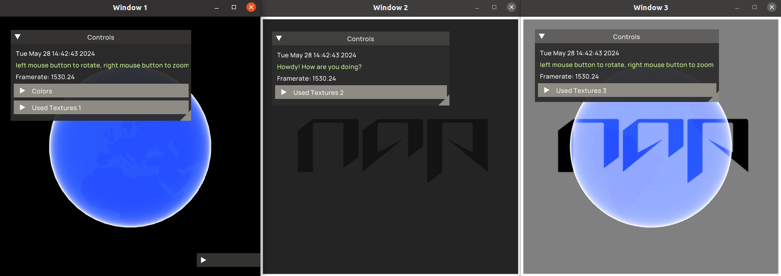
You can add as many windows to your application as you want. Take a look at the multi window demo for a working example. That demo spawns three windows and renders the same set of objects (in different configurations) to every one of them:
In your application you have to activate the window you want to render to before issuing any draw commands. This is demonstrated in the example below:
Often you want to render a selection of objects to a texture instead of a screen. But you can't render to a texture directly, you need a render target to do that for you. Every render target requires a link to a render texture. The result of the render step is stored in the texture.
Declare and set up the render target in Napkin. Next, in your application, locate the target and render your selection of items to it. This must be done in between beginHeadlessRecording and endHeadlessRecording:
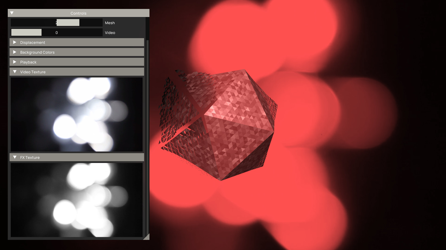
All headless (non window) render operations need to be executed within the headless recording block. Alternatively you can use the RenderToTextureComponent. This component allows you to render to a texture directly in screen space, without the need to define a render target or mesh, and can be used to apply a 'post process' render step. The video modulation demo uses this component to convert the output of a video player into a greyscale texture.
The videomodulation demo shows how to apply a grey-scale effect to a captured video frame using a render to texture component. The FX texture is used for vertex displacement:
NAP supports two camera types:
With an orthographic camera the scene is rendered using a flat projection matrix. With an orthographic camera the scene is rendered using a perspective matrix. The world space location of a camera, provided using a transform, is used to compose the view matrix. The camera projection method is used to compose the projection matrix. Both are extracted by the renderer and forwarded to the shader.
Every camera therefore needs access to a transform component that is a sibling of the parent entity. For a working example take a look at the multiwindow demo. This demo renders a set of objects to different windows using a mix of cameras.
Render layers allow you to group render components and set the sequence in which they are rendered. These layers are organized and prioritized in a RenderChain, where a layer's position in the list specifies its rank: 0 is the frontmost position (rendered first), and the last index is the rearmost. Components without an assigned layer automatically default to the front (index 0).
One useful approach for layers is to render a skybox or another background-filling object first, regardless of its position in the world. To achieve this, add a layer to the render chain named Background (rank 0) and assign it to the component responsible for rendering the background. Then, assign all other objects in the scene to the subsequent layer called Scene (rank 1). This setup ensures that the background is rendered before any other objects in your scene. Note that all objects in a layer are still sorted based on the assigned blend mode.
Render tags can be used to categorize render components. They are not ordered (unlike render layers) and multiple of them can be assigned to a render component. Each tag registers itself in the render service and receives a unique bitmask on initialization, allowing tags to be composited together into render masks.
One useful example would be to tag specific components as debug, to distinguishing them as a visual aid for debugging purposes and separating them from regular objects in your scene with (for example) the SceneTag:
The above code excludes components tagged as debug because we only include objects with the SceneTag. Tags can be combined (ORd etc.) to include objects from both sets, for example:
The above call renders all components with a Debug or Scene tag.
NAP 0.7+ introduces a new render module: the naprenderadvanced module. With a set of tools that expand (supplement) the default renderer, including: lights, shadows, cube maps, various new standard shaders and several rendering-related utilities. The RenderAdvancedService creates and manages internal resources such as render targets and textures that are bound to materials that use these advanced features.
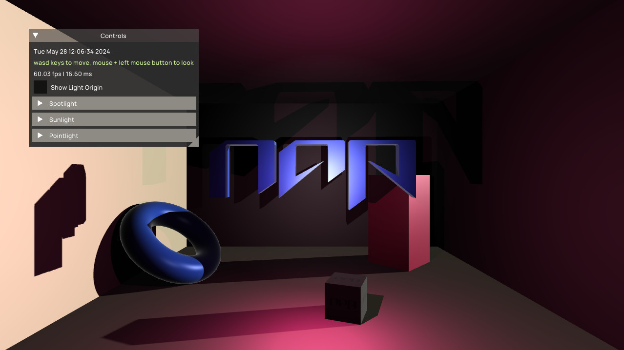
The naprenderadvanced module includes a light system that can be used to create consistent lighting setups. Every light is derived from a LightComponent and can cast shadows using shadow maps. On initialization, each light component sets up its own light uniform data and registers itself with the service.
NAP currently offers the following light types:
Check out the lightsandshadow demo for a complete demonstration of the light system:
You can use the standard BlinnPhongColorShader to quickly render a lit object. It is also possible to write a custom Shader that is compatible with the lighting system. For a guide to set this up, please refer to the Custom Lights section below. Settings related to the material (such as color etc..) can be set by the user in Napkin. In the case of the blinn phong shader these include ambient, diffuse and specular. The maximum number of lights per scene is always limited to getMaximumLightCount, additional lights are ignored.
Note that you must call pushLights() manually to update all the light uniforms (location etc.) if you don't use shadows.
Every (default) light can cast shadows using shadow maps. These shadow maps need to be rendered first before they can be applied, which is done during the headless render pass in your app's render() hook.
If you don't need or want to render shadow maps each frame you can update the light uniforms manually using a call to pushLights(). Consider using a tag to only update components that are lit, for example:
For a complete demonstration of the light system, check out the new lightsandshadow or spotlight demo.
In order for shaders to be compatible with the light system they must include a specific uniform struct with the name light, and optionally shadow when shadows are supported. Make sure to enable the GL_GOOGLE_include_directive extension in your shader file to enable shader includes. Include the following files:
Please note that NAP is only able to locate these module-specific shader files if your application depends on naprenderadvanced.
This will include the Light data structure in your shader as defined in light.glslinc, which looks like this:
When implementing a custom shader that is compatible with the light system you should define the following uniform struct and read the data of count lights.
Below is a simple approach to mixing lights using the computeLight function in blinnphongutils.glslinc. isLightEnabled in light.glslinc checks whether the light is enabled by reading the appropriate bit flag.
For a complete example of how to write a compatible shader for NAP's light system, refer to the blinnphongcolor shader in the naprenderadvanced/data/shaders folder. This also shows how to set up quad and omni shadow mapping.
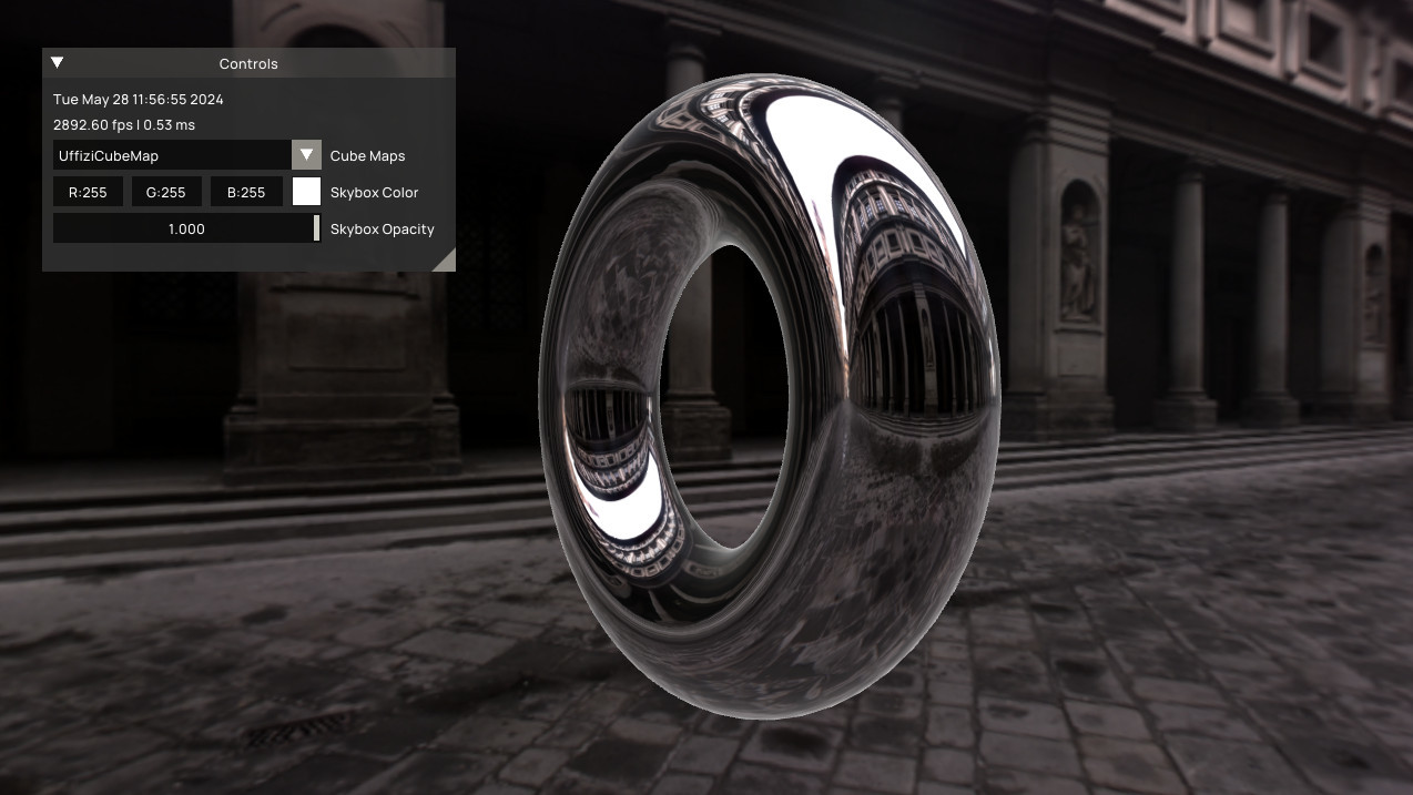
CubeMapFromFile takes an equirectangular image as input and turns it into a CubeMap, which can be used to - for example - render a sky box using the SkyBoxShader or add environmental reflections to objects using the BlinnPhongShader, which has environmentMap and reflection inputs for this purpose.
Check out the SkyBox demo to see how to work with cube maps: